CAM, or Computer-Aided Manufacturing, is a fundamental concept in the field of mechanical engineering. It refers to the use of computer software and technology to automate and optimize various aspects of the manufacturing process. CAM plays a crucial role in transforming design concepts and CAD models into physical products efficiently and accurately. Here are the key components and concepts associated with CAM in mechanical engineering:
- Toolpath Generation: One of the primary functions of CAM is to generate toolpaths for machining operations. These toolpaths provide instructions to machine tools, such as CNC (Computer Numerical Control) machines, on how to move and control cutting tools to shape and finish a workpiece according to the design specifications.
- Types of Machining: CAM software supports a wide range of machining processes, including milling, turning, drilling, grinding, and electrical discharge machining (EDM). Each of these processes requires specific toolpaths and strategies.
- Material Removal Strategies: CAM software offers various strategies for material removal, such as roughing, finishing, contouring, and pocketing. These strategies are selected based on factors like material type, part geometry, and desired surface finish.
- Tool Selection and Optimization: CAM systems help select the appropriate cutting tools, toolholders, and cutting speeds and feeds. They also optimize toolpaths to minimize tool wear, reduce machining time, and maximize tool life.
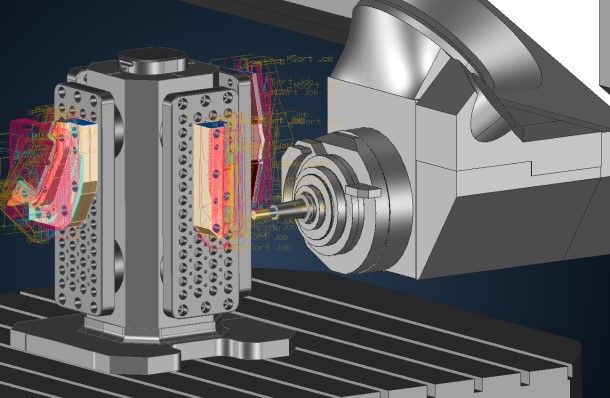
- Simulation: CAM software often includes simulation capabilities to visualize and validate toolpath movements and machining processes. This helps identify and rectify potential issues before actual machining, reducing the risk of errors and collisions.
- Nesting and Material Utilization: CAM tools can optimize the placement of parts on raw material sheets or stock to minimize waste and maximize material utilization, which is particularly important for cost-efficiency.
- Post-Processing: CAM software generates machine-specific G-code or other control code formats required by CNC machines. These post-processed files are then used to control the machining process.
- Multi-Axis Machining: CAM systems support multi-axis machining for complex parts. This includes 3-axis, 4-axis, and 5-axis machining, allowing for more intricate geometries and greater flexibility in manufacturing.
- Toolpath Editing: Engineers can fine-tune and edit generated toolpaths in CAM software to accommodate specific manufacturing requirements or address issues identified during simulation.
- Integration with CAD: CAM software often integrates seamlessly with CAD systems, allowing for a streamlined workflow where designs created in CAD are directly translated into manufacturing toolpaths.
- Quality Control: CAM can incorporate inspection and quality control processes to ensure that machined parts meet design specifications and tolerances.
- Production Planning: CAM software aids in production planning by scheduling jobs, managing tool and material inventory, and optimizing the overall manufacturing workflow.
- Cost Reduction: By automating and optimizing manufacturing processes, CAM contributes to cost reduction through increased efficiency, reduced material waste, and improved accuracy.
In summary, CAM in mechanical engineering bridges the gap between design (CAD) and manufacturing, enabling the efficient and precise production of mechanical components and products. It leverages computer technology to automate processes, reduce errors, improve machining efficiency, and ultimately deliver high-quality, cost-effective manufactured goods.